33+ directional coupler block diagram
Port 4 The Isolated. Below is a simplified version of the list of the four ports of the directional coupler.

Product Catalog
Wikipedia Most of the signal incoming at Port 1 P1 will pass through to P2.
. Heres a couple of ways of drawing a directional coupler in a block diagram. A directional coupler is a measurement device that is inserted into the transmission line between an RF sourcesuch as a signal generator vector network analyzer. Port 1 The Input Port.
A block diagram symbol for a directional coupler. Block Type Directional Couplers 561 Series Couplings of 3 6 10 20 30 40and 50 dB available. Download scientific diagram Block diagram of a 3D geometrical configuration of 3 dB quadrature hybrid coupler upper ground is removed for clear illustration b Coupling section.
Port 3 The Coupled Signal Port. Port 1 The Input Port. Port 2 The Output Port.
A block diagram symbol for a directional coupler is shown in the following figure. C1 and C2 have 500-V. As it can be seen from the figure.
A Directional coupler is a device that samples a small amount of Microwave power for measurement purposes. R1 and R2 are 47- or 51-Ω 12-W resistors. A directional coupler is often used for sampling a small portion of the signal power.
Adapters Amplifiers Attenuators Bias Tees Cables Couplers DC Blocks Equalizers Filters Frequency Mixers Frequency Multipliers Impedance Matching Pads Limiters. Fig 1946Schematic diagram of the high-power directional coupler. For example we might measure the output power of the coupled port eg P 3 and then we can.
An electrical connector is an electro-mechanical device used to join electrical terminations and create an electrical circuit. Electrical connectors consist of plugs male-ended and jacks. D1 and D2 are germanium diodes 1N34 or equiv.
A block diagram symbol for a directional coupler. The power measurements include incident power reflected power.
2
2
Application Of Accelerators And Storage Rings Springerlink
2

Controls Instruments For The Me 262a War Thunder Messerschmitt Messerschmitt Me 262
2
2

Product Map For Rf Components And Modules Connectivity Tech Notes Rf Components And Modules Tdk Product C Base Transceiver Station Inductors Connection

Product Map For Rf Components And Modules Connectivity Tech Notes Rf Components And Modules Tdk Product C Base Transceiver Station Inductors Connection
Class Definition For Class 137 Fluid Handling

Application Of Accelerators And Storage Rings Springerlink
Class Definition For Class 333 Wave Transmission Lines And Networks
Application Of Accelerators And Storage Rings Springerlink
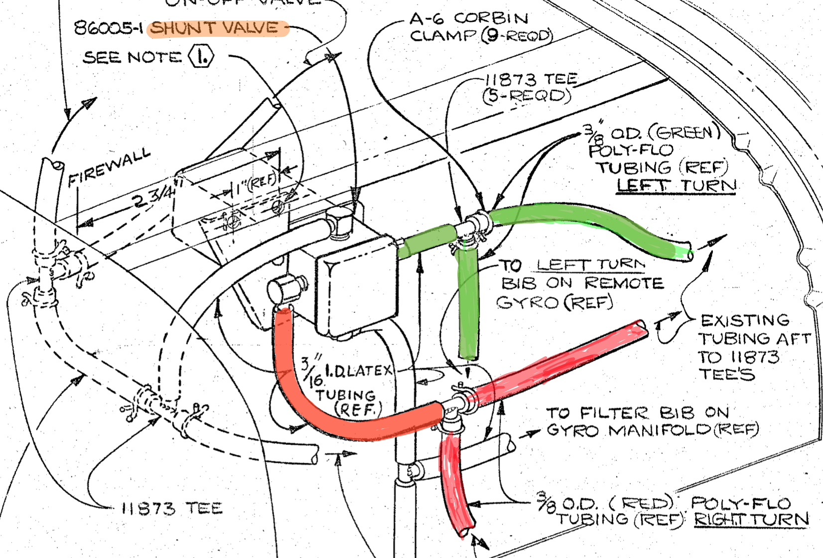
How To Use Brittain Autopilot Page 2 Vintage Mooneys Pre J Models Mooneyspace Com A Community For Mooney Aircraft Owners And Enthusiasts
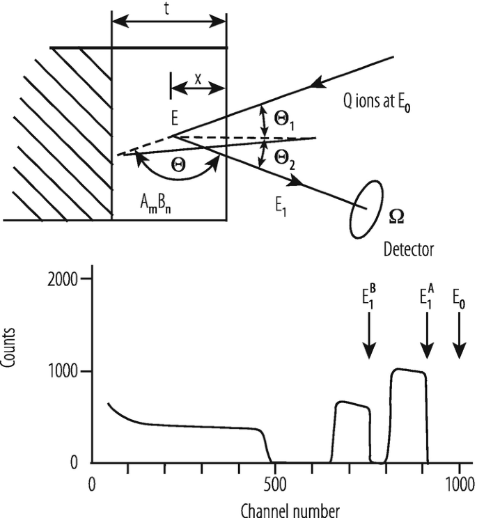
Application Of Accelerators And Storage Rings Springerlink
2
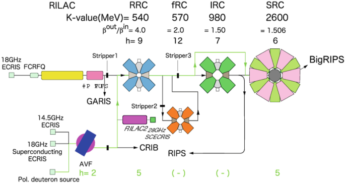
Application Of Accelerators And Storage Rings Springerlink